
Free online use case diagram maker
Use case diagram generator for actors, goals and system boundaries
Write who uses a system and what they want from it, and get a correct UML use case diagram: stick-figure actors outside the system boundary, use cases as ellipses inside it, associations, «include» and «extend» arrows pointing the right way, extension points, conditions and generalization. Type it as text or add it with the builder. Free, private, with SVG, PNG and PDF export.
Everything runs in your browser: nothing is uploaded, and the diagram is drawn exactly from your code. Undo with Ctrl+Z.
Step by step
How to make a use case diagram
Six steps that work for a lab information system, a booking app or a software engineering assignment.
- 1
Name the system
Decide what the boundary contains: the laboratory information system, the booking app, the ATM. Everything inside it is the system’s job; everything outside is an actor. Write system "Name" on the first line under the header.
- 2
List the actors
Write the roles that interact with the system, not people’s names: Scientist, Lab manager, Clinical monitor. Add right after an actor that only supports the system, such as another system it calls.
- 3
Add one use case per goal
Each use case is a goal an actor reaches in one sitting, named verb + object: Register sample, Book instrument time. Keep it at the level of “what”, not the screens or clicks.
- 4
Connect actors to their use cases
Draw an association (Actor -- UseCase) from each actor to every use case it takes part in. An actor with no line, or a use case no actor reaches, is usually a gap in the model.
- 5
Factor out shared and optional steps
When several use cases always run the same step (Log in), add it once with ..> : include. When a step only happens sometimes (Flag as urgent), point it at its base with ..> : extend and say when, in [brackets].
- 6
Check and export
Read every line aloud: “Scientist registers sample”, “Request analysis always includes Log in”. Then download SVG or PDF for a report, or PNG for slides.
Templates
Use case diagram examples to start from
Seven complete use case diagrams, from a two-actor course portal to a clinical trial data system. Open one in the editor and rename the actors and use cases.
Notation reference
Use case diagram symbols and their code
The UML 2.5.1 use case symbols, what each means and how to write it here. Add puts a working example into the laboratory information system diagram.
| Symbol | Element and meaning | Code in this tool |
|---|---|---|
Actor A role outside the system that uses it (primary actors on the left). | actor Scientist | |
Secondary or system actor An outside system or role the system calls on, drawn on the right. | actor "Freezer monitor" as Monitor <<system>> right | |
Use case A goal an actor reaches with the system, named verb + object. | usecase "Register sample" as Register | |
Use case with extension points Points where an extending use case may add behaviour, listed in a compartment. | usecase "Request analysis" as Request extension points: urgent sample | |
Subject (system boundary) The system that owns the use cases, named at the top; actors stay outside. | system "Laboratory information system" | |
Association The actor takes part in the use case. Usually a plain line. | Scientist -- Register | |
Association with arrowhead Optional: shows which side starts the interaction. | Scientist --> Register | |
«include» The base use case always runs the included one. Arrow from base to included. | Base ..> Included : include | |
«extend» Optional behaviour added to a base use case. Arrow from the extension to the base. | Extension ..> Base : extend | |
Extend condition and extension point A comment on the extend arrow: Condition: {…} and the extension point used. | E ..> B : extend [condition] (point) | |
Generalization The child actor or use case is a kind of the parent. Triangle at the parent. | Manager --|> Scientist | |
Note (comment) A remark attached to an actor or a use case. | note for Register : text |
Common mistakes
Six use case diagram mistakes and their fixes
Steps drawn as use cases
WrongEllipses named Enter barcode, Click save, Validate field, joined by include arrows.
RightName goals an actor would pay for: Register sample. Put the steps in the use case description, or in an activity diagram.
«include» and «extend» arrows reversed
WrongLog in ..> Register : include, or Request ..> Flag as urgent : extend.
RightInclude points from the base to the step it always runs (Register ..> Log in); extend points from the optional use case to its base (Flag as urgent ..> Request).
Actors inside the system boundary
WrongThe database or the lab manager drawn inside the rectangle.
RightActors are outside by definition. If something is part of the system, it is not an actor; if it is outside and interacts, it is.
Lines between actors
WrongAn association from Scientist to Lab manager to show who reports to whom.
RightUse case diagrams do not show communication between actors. Use generalization (Lab manager --|> Scientist) if one role is a kind of the other; otherwise leave it out.
People’s names as actors
WrongActors called Dr Chen and Maria.
RightName roles: Principal investigator, Study coordinator. One person can play several roles, and the model should survive staff changes.
A flowchart drawn with ellipses
WrongUse cases chained by arrows in the order they happen.
RightA use case diagram has no sequence. Order belongs in the description, a sequence diagram or an activity diagram.
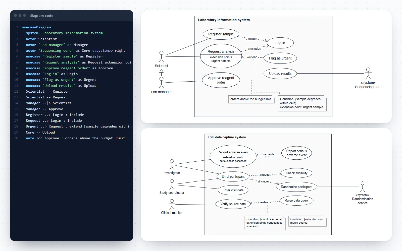
How this use case diagram maker works
Write the model as short lines of text or build it from forms; the diagram is redrawn as you type and every change can be undone.
- Code tab: one statement per line (actor, usecase, system, note, or two names joined by an arrow), with line numbers and plain-English messages that name the line to fix.
- Build tab: add actors (left or right), use cases with extension points, associations, «include», «extend» with a condition and extension point, generalization and notes. Names you type that are not in the diagram yet are declared for you.
- The layout is automatic and repeatable: primary actors on the left, secondary actors on the right, use cases inside the boundary, included and extending use cases one column further in. The same code always gives the same drawing.
- Style tab: four figure styles, the text size and a compact spacing option. Seven templates, from a two-actor course portal to a clinical trial data system.
- Saved in your browser as you work; nothing is uploaded and there is no account.
What is a use case diagram?
A use case diagram is the UML diagram of a system’s requirements from the outside: who uses the system (actors), what they use it for (use cases), and where the system ends (the subject, often called the system boundary).
- It answers “what must the system do, and for whom?”, not “how does it work inside?”. Each use case stands for a goal that gives an actor a result of value.
- The diagram is a map, not the whole requirement: each use case is normally written up as a text description with its steps, alternatives and exceptions.
- Use cases came from Ivar Jacobson’s work in the late 1980s and became part of UML. The current standard is UML 2.5.1 (Object Management Group, 2017), clause 18 UseCases.
- UML classifies the use case diagram as a behavior diagram. It sits alongside activity, state machine and the interaction diagrams such as the sequence diagram.
Actors: primary, secondary and system actors
An actor is a role played by someone or something outside the system that interacts with it. One person can play several roles, and one role can be played by many people.
- Primary actors start use cases to reach their own goals: the scientist who registers a sample. By convention they are drawn on the left.
- Secondary (supporting) actors are used by the system to complete a use case: a sequencing core that uploads results, a payment provider, a randomisation service. They are drawn on the right; write right after the actor.
- An actor can be another system or a device. UML draws every actor as a stick figure by default; the keyword «system» in this tool marks one that is a computer system.
- Name actors after roles (Lab manager, Clinical monitor), never after a person (Dr Smith) or a department that has no single goal.
- Time can trigger a use case (a nightly backup). Many teams draw a Timer or Scheduler actor for it; the use case description says what triggers it either way.
Use cases and the system boundary
A use case is drawn as an ellipse with its name inside. The subject that owns the use cases is a rectangle around them, named at the top; actors always stand outside it.
- Name a use case as a short verb phrase from the actor’s point of view: Request analysis, Approve reagent order, Withdraw cash.
- One use case is one complete goal, finished in one session. Enter sample ID, Click save and Validate barcode are steps inside a use case, not use cases.
- The boundary makes scope explicit: if a use case is not inside it, the system does not do it. Drawing the boundary is often where a team discovers it disagrees about scope.
- Extension points, the places where optional behaviour can be inserted, are listed in a compartment under the name, headed “extension points”. Add them with extension points: a, b at the end of a usecase line.
«include» vs «extend»: which one, and which way the arrow points
Both are dashed arrows with an open arrowhead and a keyword, and they are the most confused part of use case diagrams. The difference is whether the extra behaviour always or only sometimes happens, and the arrows point in opposite directions.
- «include»: the base use case always runs the included one. The arrow goes from the base to the included use case: Request analysis ..> Log in : include. Use it for a step shared by several use cases.
- «extend»: the extending use case adds optional behaviour to a base use case, only when a condition holds. The arrow goes from the extending use case to the base: Flag as urgent ..> Request analysis : extend.
- The base use case of an extend is complete without the extension, and does not know about it. A base use case is not complete without what it includes.
- The condition and the extension point of an extend are shown in a comment attached to the arrow, written Condition: {…} and extension point: …. Here, write them as ..> Base : extend [condition] (extension point).
- Use both sparingly. A diagram full of include and extend arrows is usually a functional decomposition (steps of a program), which belongs in an activity diagram instead.
Generalization of actors and use cases
Generalization is drawn as a solid line with a hollow triangle pointing at the more general element. It works between two actors or between two use cases, never between an actor and a use case.
- Actor generalization: a Lab manager is a Scientist with extra rights, so Lab manager --|> Scientist. The lab manager inherits every association of the scientist and adds Approve reagent order.
- Use case generalization: Pay by card and Pay by invoice are specialised forms of Pay for order. The child use cases inherit the parent’s meaning and replace or add steps.
- Generalization says “is a kind of”, so check the sentence: “a Registered customer is a kind of Customer” works; “Log in is a kind of Register sample” does not.
- This tool draws an actor’s specialisations under it in the same column, and a specialised use case one column to the right of its parent, so the triangles never hide behind other shapes.
The use case description behind each ellipse
A use case diagram names the use cases; the text description says what happens in each. Most courses and requirement templates ask for both.
- A typical description lists the name, primary actor, stakeholders and interests, preconditions, the main success scenario as numbered steps, extensions (alternatives and failures) and postconditions.
- The extensions of the text and the «extend» arrows of the diagram tell the same story: an optional path in the steps can become an extending use case when it is large enough to describe on its own.
- Write the steps as an exchange between the actor and the system (“The scientist enters the sample barcode. The system shows the sample record.”), without user interface detail.
- When the order of the messages matters, draw one scenario as a sequence diagram; when the steps branch and join, draw an activity diagram.
Use case diagrams for laboratory and research software
Research groups, core facilities and clinical teams write requirements for software too, and a one-page use case diagram is the quickest way to agree on scope with a vendor or a developer.
- Laboratory information management system (LIMS): register samples, request analyses, approve orders, upload results from a core facility, with log in included and urgent samples as an extension.
- Clinical trial data capture: enrol participants (always checking eligibility and randomising), record adverse events, verify source data and raise queries, with the randomisation service as a secondary actor.
- Core facility booking: book and cancel instrument time, check training records, join a waiting list when the slot is taken, and charge usage to a grant through the billing system.
- Electronic lab notebooks, sample biobanks, instrument data pipelines and teaching platforms all fit the same pattern: roles on the outside, goals on the inside.
Use case diagram AI: generating the diagram from text
A chat assistant can draft a list of actors and use cases from a requirements document. This page turns that list into an exact diagram and checks it against the UML rules.
- Ask the assistant for lines in the syntax shown under the code editor (actor, usecase, --, ..> : include, ..> : extend, --|>), or paste plain lists and turn them into lines with the builder.
- The parser rejects what UML does not allow: an association between two actors or two use cases, include or extend touching an actor, generalization between an actor and a use case, and use of a name that was never declared.
- Then review the model the way a reviewer would: are the use cases goals rather than steps, does every actor have a use case, and is each include or extend arrow pointing the right way?
- Nothing is guessed: the drawing contains exactly what the code says, and the same code always gives the same layout.
An exact, editable use case diagram generator
Every element you write appears once, in standard notation, and nothing is added. The output is ready for a thesis, a requirements document or a software engineering assignment.
- SVG and PDF keep real text, so the diagram can be edited in Illustrator, Inkscape or PowerPoint and stays sharp at any size. PNG exports at 2× or 4×.
- The Publication style prints black lines on white, as textbooks and journals print UML; Grey fill, Blue accent and Dark suit slides and posters.
- The code is plain text, so it can live next to the project’s other documents and be pasted back here to edit the diagram later.
Frequently asked questions
Is this use case diagram generator free?
Yes. No sign-up, no watermark and no limits on size or exports. It runs entirely in your browser, nothing you type is uploaded, and your diagram is saved on your device so it is still there next time.
How do I make a use case diagram?
Name the system with system "Name", add the actors (actor Scientist), add one use case per goal (usecase "Register sample" as Register) and connect them (Scientist -- Register). Add «include», «extend» and generalization where they apply. The diagram redraws as you type, or use the Build tab, which writes each line for you.
What is the difference between «include» and «extend»?
«include» is behaviour the base use case always runs, such as Log in; the arrow goes from the base to the included use case. «extend» is optional behaviour that runs only when a condition holds, such as Flag as urgent; the arrow goes from the extending use case to the base, and the base is complete without it.
Which way do the include and extend arrows point?
Include: from the use case that needs the step to the step (Register sample → Log in). Extend: from the optional use case to the one it extends (Flag as urgent → Request analysis). Both are dashed with an open arrowhead and the keyword in guillemets.
How do I show extension points and the condition of an extend?
Add extension points: name to the end of the extended use case’s line, and write the extend as Extension ..> Base : extend [condition] (extension point). The use case gets an “extension points” compartment, and the condition and point appear in a comment attached to the arrow, as UML specifies.
What is a system boundary in a use case diagram?
The rectangle around the use cases, named after the system (UML calls it the subject). It shows the scope: use cases inside are what the system does, and actors outside are who or what it serves. Here, system "Name" draws it, and every use case is placed inside.
What is the difference between a primary and a secondary actor?
A primary actor starts a use case to reach its own goal (the scientist registering a sample). A secondary actor is called on by the system to complete it (a payment provider, a sequencing core). Write right after a secondary actor to draw it on the right.
Can an actor be another system?
Yes. An actor is any role outside the system that interacts with it: a person, a device or another software system. Add <<system>> after the name to mark it, for example actor "Randomisation service" as IWRS <<system>> right.
How do I show that one actor is a special kind of another?
With generalization: Lab manager --|> Scientist draws a hollow triangle at Scientist. The lab manager then takes part in everything the scientist does, plus its own use cases. The same arrow works between two use cases.
Can I generate a use case diagram with AI?
You can ask a chat assistant to list the actors and use cases from your requirements in the syntax shown under the editor, then paste the lines here. The parser rejects connections UML does not allow and names the line, and the drawing shows exactly what the code says, so you can review the model before you use it.
How many use cases should one diagram have?
As many as fit on a page and stay readable, usually under about fifteen. For a larger system, draw one diagram per subsystem or per main actor, each with its own boundary.
Is a use case diagram the same as a use case description?
No. The diagram shows which use cases exist and who takes part; the description, a structured text, gives each use case’s preconditions, main success steps, alternatives and results. A requirements document normally has both.
Does the code work in GitHub or PlantUML?
The syntax is this tool’s own, chosen so the drawing can follow UML exactly (stick figures outside the boundary, extension points, conditions on extend). It looks familiar if you know PlantUML, but it is not the same language. Download the code as a text file to keep it, and paste it back here to edit.
Which file format is best for a report or a thesis?
SVG or PDF: they are vector formats with real text, sharp at any size and editable in Illustrator, Inkscape or PowerPoint. Use PNG at 2× or 4× for slides and web pages.
Related diagram tools
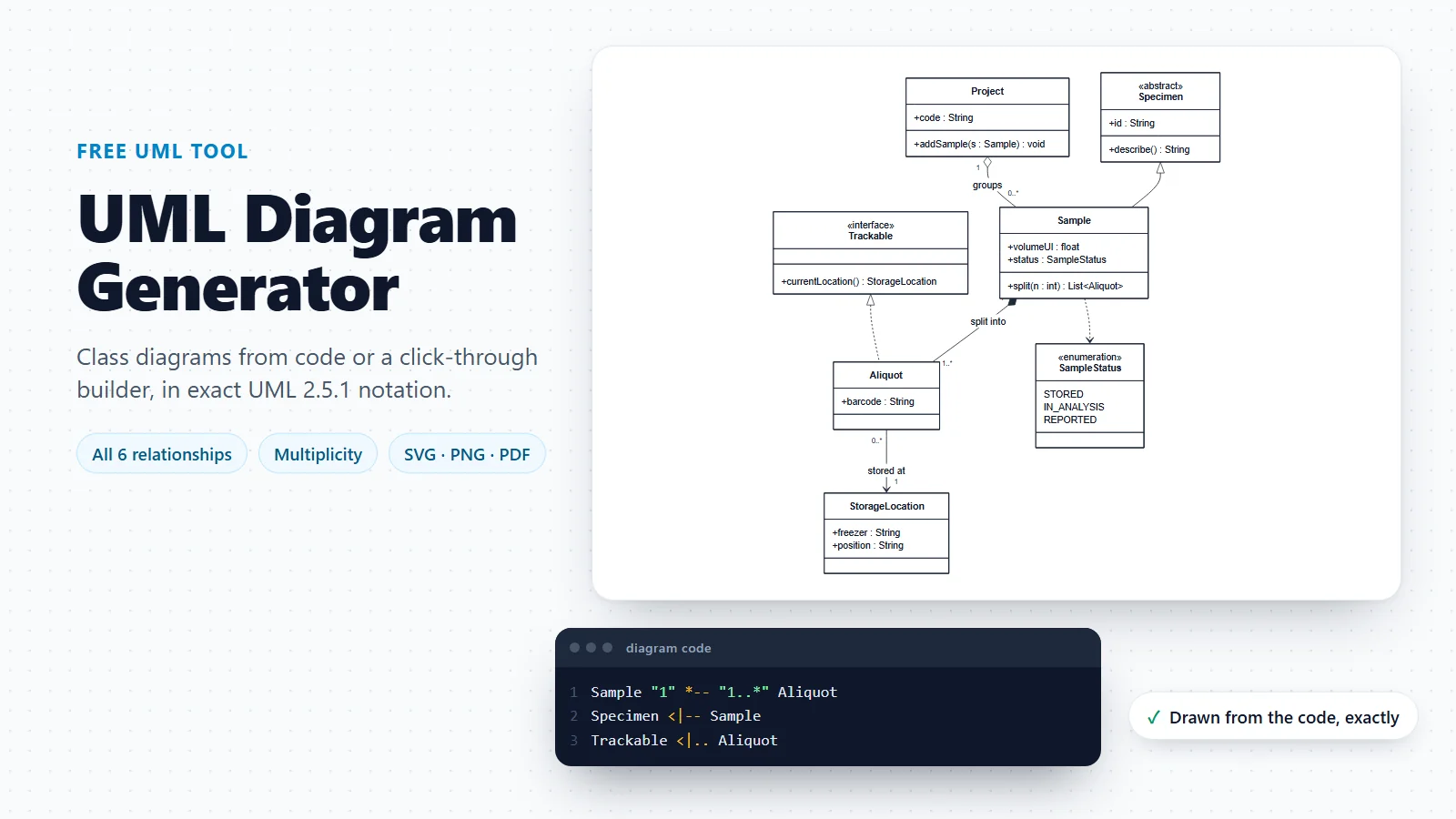
UML Diagram Generator
Class diagrams with every UML relationship, and a guide to the 14 UML diagram types.
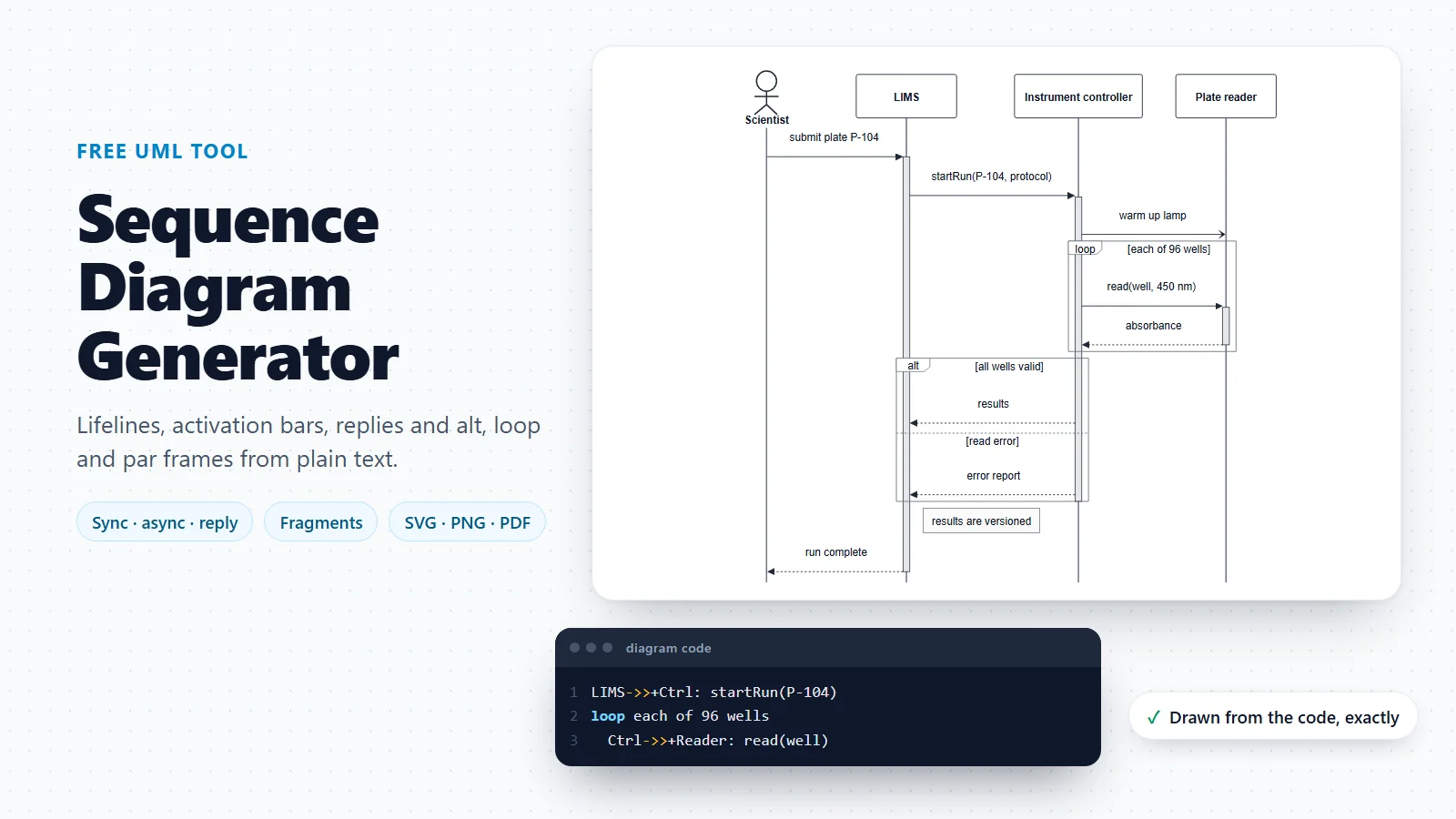
Sequence Diagram Generator
One use case scenario as messages between participants, in time order.
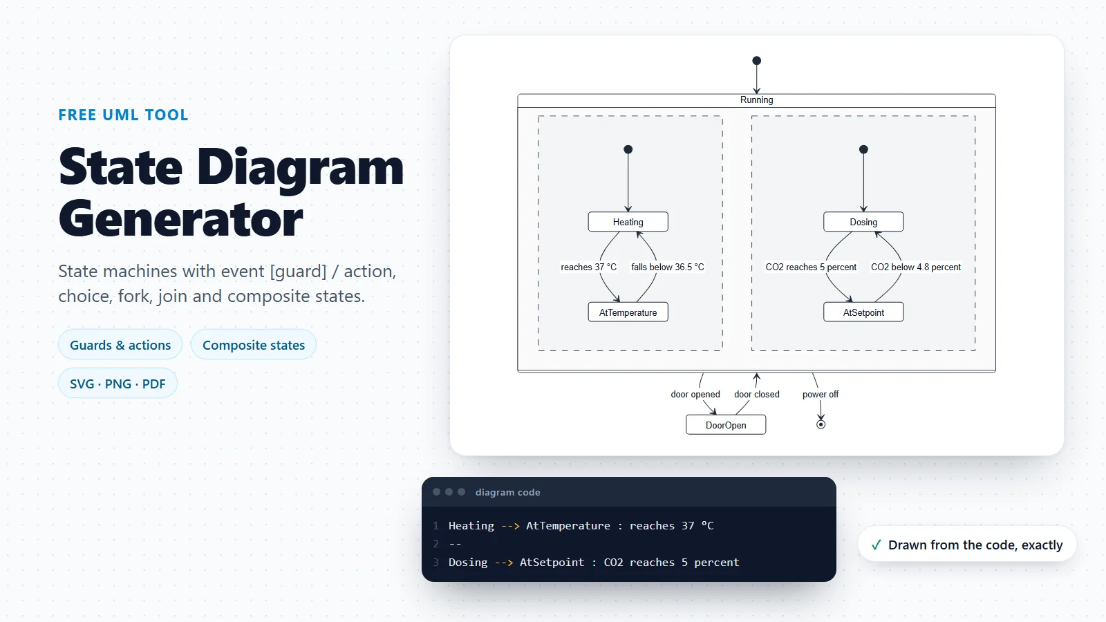
State Diagram Generator
The lifecycle of one object, such as a sample, across every use case that changes it.
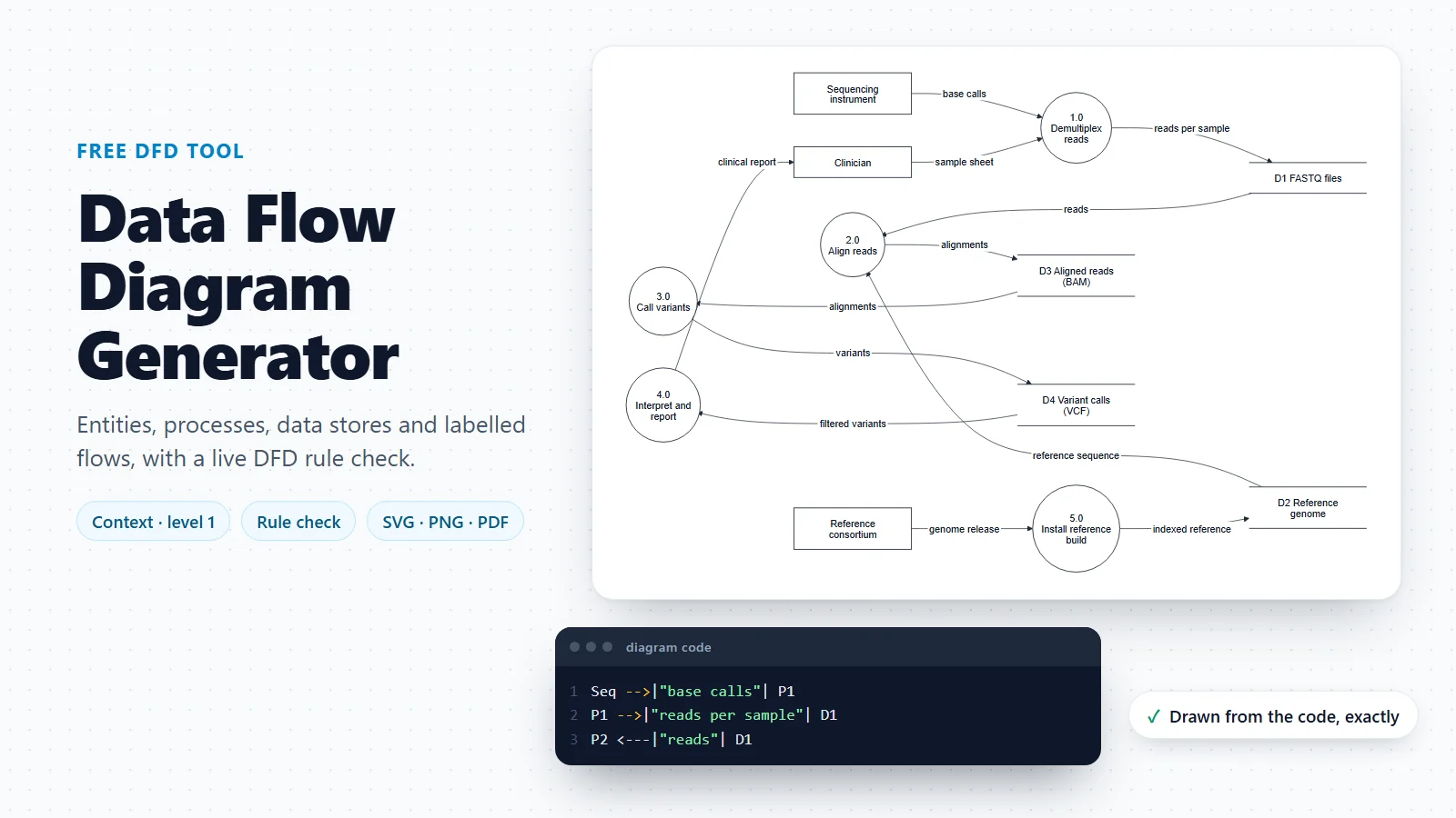
Data Flow Diagram Generator
Processes, data stores and external entities: how data moves through the same system.
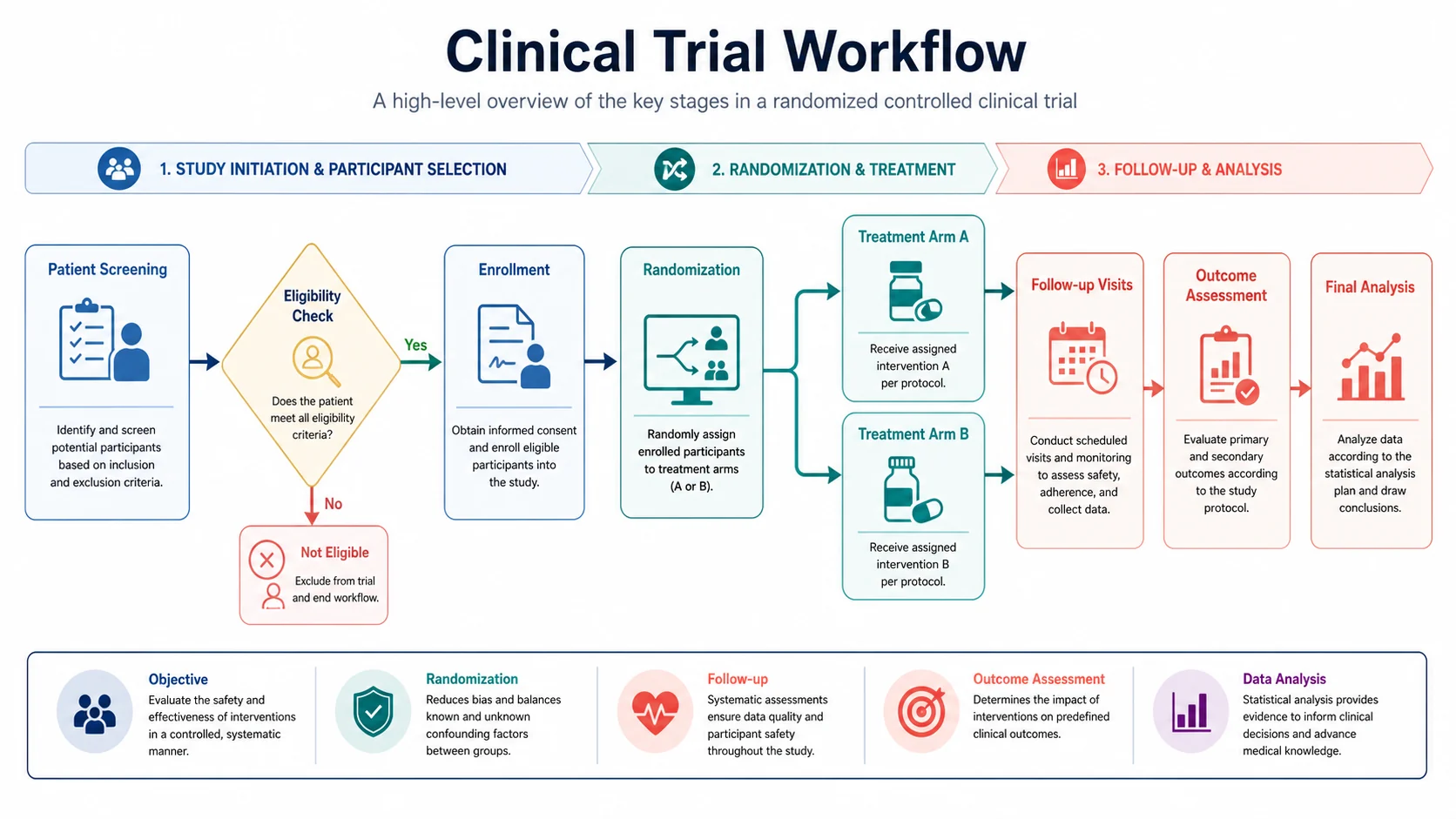
Workflow Diagram Generator
A flowchart of the steps inside one use case, with decisions and loops.
Need the steps inside a use case?
A use case diagram names the goals; the order of the steps belongs in a flowchart or an activity-style diagram. The workflow diagram generator turns a short description into one.
Open the workflow diagram generatorLast checked: November 17, 2026. Sources: Object Management Group, UML 2.5.1 specification, clause 18 UseCases; Jacobson, Christerson, Jonsson and Övergaard, Object-Oriented Software Engineering: A Use Case Driven Approach (Addison-Wesley, 1992); Cockburn, Writing Effective Use Cases (Addison-Wesley, 2001). The laboratory, clinical and facility templates are illustrative models, not the requirements of any real product.