
Free state machine diagram maker
State diagram generator for UML state machines and state transition diagrams
Describe the states of an instrument, a sample, an order or a protocol and the events that move between them, and get an exact UML state machine diagram: initial and final states, transitions labelled event [guard] / action, choice diamonds, fork and join bars, composite states and concurrent regions. Type the transitions as text or add them with the builder. Free, private, with SVG, PNG and PDF export.
Everything runs in your browser: nothing is uploaded, and the diagram is drawn exactly from your code. Undo with Ctrl+Z.
Step by step
How to draw a state machine diagram
Six steps that work for a sample lifecycle, an instrument controller or a classroom finite state machine.
- 1
List the states
Write down the conditions the thing can be in while it waits for something to happen: Idle, Heating, Cycling, Final hold. A state lasts for a while; an event happens at a moment.
- 2
Mark where it starts and can end
Draw the initial transition from [*] to the first state. If the object can finish, add transitions to [*] as a target, which draws the final state.
- 3
Add the transitions
For each event that changes the state, add From --> To : event [guard] / action. Only the event is usual; add a guard in brackets when the move depends on a condition, and an action after a slash for what happens on the way.
- 4
Use choice, fork and join where needed
A choice diamond splits one transition by its guards ([QC passed] / [QC failed]). A fork bar starts parallel branches and a join bar waits for all of them.
- 5
Group with composite states
When several states share the same way out (an abort that applies to every step), put them inside a composite state and draw that transition once from its border. Split it with -- for concurrent regions.
- 6
Check and export
Make sure every state can be reached and, unless it is meant to be final, can be left. Then download SVG or PDF for documents, or PNG for slides.
Templates
State machine diagram examples to start from
Eight complete state machines, from a two-state turnstile to the TCP connection states. Open one in the editor and adapt the states and transitions.
Notation reference
State machine diagram symbols and their code
The UML 2.5.1 state machine symbols, what each means and how to write it here. Add puts a working example into the laboratory sample diagram; rows without code are UML symbols this renderer does not draw.
| Symbol | Element and meaning | Code in this tool |
|---|---|---|
Initial pseudostate Where the state machine, or a region, starts. No event or guard. | [*] --> Idle | |
Final state The region has completed. | Done --> [*] | |
State A condition the object stays in until an event occurs. | Idle | |
State with internal activities entry, do and exit behaviours listed under the name. | state "Heating" as Heating
Heating : entry / lock lid | |
Transition Trigger [guard] / effect; each part optional. | A --> B : event [guard] / action | |
Choice Picks one path by its guards when reached; use [else] for the rest. | state c <<choice>> | |
Fork and join A bar that splits into concurrent branches, or waits for all of them. | state f <<fork>>
state j <<join>> | |
Composite state A state with its own sub-states and initial state. | state Running {
[*] --> Warmup
} | |
Concurrent regions Orthogonal regions inside a composite state, active at the same time. | state Running {
…
--
…
} | |
Note A comment attached to a state. | note right of A : text | |
Junction Merges or splits transitions with guards evaluated in advance. | No separate symbol here; a choice diamond reads the same in most diagrams. | |
Shallow history Re-enters the last active sub-state of a composite state. | Not drawn by this tool; add a note such as “returns to last sub-state (H)”. | |
Deep history Re-enters the last active sub-state at every nesting level. | Not drawn by this tool; describe it in a note. | |
Terminate Ends the whole state machine at once, unlike a final state. | Not drawn by this tool; use a final state and a note. |
Common mistakes
Six state diagram mistakes and their fixes
Activities drawn as states
WrongStates named Calculate result or Send email, which happen and finish.
RightName states after conditions that last (Calculating, Waiting for reply); put short actions on transitions after the slash, or as entry / do / exit activities.
Guards that overlap or leave gaps
Wrong[volume > 50] and [volume < 50]: nothing happens at exactly 50.
RightMake the guards cover every case exactly once: [volume ≥ 50] and [else].
Dead-end and unreachable states
WrongA Rejected state with no way out, or an Archived state no transition leads to.
RightCheck that every state can be reached from the initial state and, unless it is meant to end there, has a transition out or to the final state.
The same transition repeated from every sub-state
WrongAn abort arrow from each of Denaturation, Annealing and Extension.
RightGroup them in a composite state (Cycling) and draw abort once from its border.
Event, guard and action in the wrong order
Wrong/ lock lid [lid closed] start.
RightAlways event [guard] / action: start [lid closed] / lock lid.
A flowchart labelled as a state diagram
WrongBoxes for steps joined by arrows with no events, describing a procedure.
RightIf the boxes are steps, draw a flowchart or activity diagram; a state diagram needs events that cause each transition.
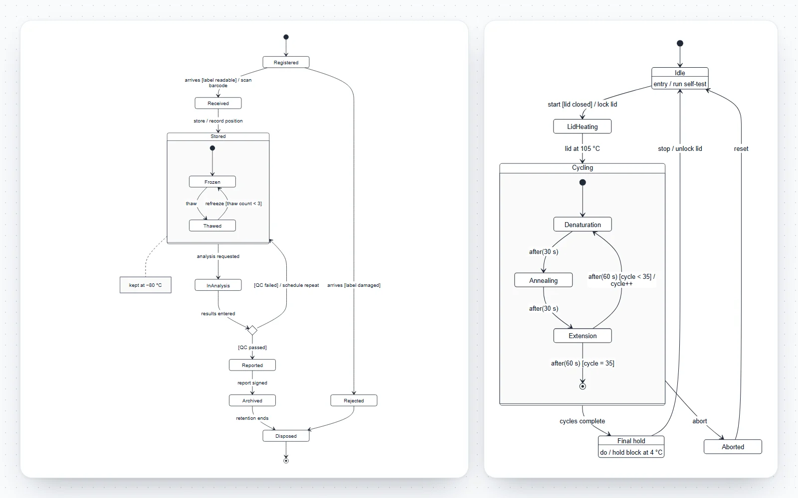
How this state machine diagram maker works
Type transitions in the code editor or build them from forms; both stay in sync with the diagram, and every change can be undone.
- Code tab: one transition per line, with line numbers and plain-English error messages on the line that needs fixing. The last good diagram stays on screen while you edit.
- Build tab: add states with internal activities, transitions with event, guard and action, choice diamonds, fork and join bars, composite states, concurrent regions and notes.
- Style tab: top-to-bottom or left-to-right layout, four figure styles and the text size.
- Eight templates: a laboratory sample lifecycle, a PCR thermocycler, a CO₂ incubator with concurrent control loops, the cell cycle, an order with fork and join, a turnstile, a traffic light and the TCP connection states.
- Saved in your browser as you work; nothing is uploaded.
What is a state machine diagram?
A state machine diagram, often called a state diagram or state transition diagram, shows the states an object or system can be in, the events it responds to, and the transitions those events cause. UML 2.5.1 calls it a behavior state machine.
- A state is a condition that lasts: a thermocycler is Idle, Heating or Cycling; a sample is Stored or In analysis.
- An event is something that happens at a moment: a button press, a message, a timer running out, a value crossing a threshold.
- A transition is the move from one state to another when an event occurs and its guard is true; the action on it runs during the move.
- The UML notation descends from David Harel’s statecharts (1987), which added nesting, concurrency and history to classic state transition diagrams.
- A state diagram covers every scenario for one object. A sequence diagram, by contrast, shows one scenario across several participants.
Transitions: event [guard] / action
UML writes a transition label in three optional parts, always in this order: the trigger (event), the guard in square brackets, and the effect (action) after a slash.
- start [lid closed] / lock lid: on the start event, if the lid is closed, lock it and move to the next state.
- Time events are written after(30 s); change events are written when(temperature > 37 °C).
- A transition with no event is a completion transition: it fires as soon as the state has finished its work, such as when a composite state reaches its final state.
- A self-transition (Locked --> Locked : push / sound alarm) leaves the state and enters it again, so its exit and entry activities run. An internal transition, written inside the state, does not.
- Guards must not overlap or leave gaps: on a choice, [QC passed] and [QC failed], or one guard and [else], so exactly one path is always taken.
States, internal activities and the final state
A simple state is a rounded rectangle with its name. Below a dividing line it can list internal activities that run while the object is in that state.
- entry / lock lid: runs every time the state is entered, whichever transition led there.
- do / hold block at 4 °C: runs while the object stays in the state and can be interrupted by an outgoing transition.
- exit / log temperature: runs every time the state is left.
- In the code, give the state a display name with state "Final hold" as FinalHold, then add one line per activity: FinalHold : do / hold block at 4 °C.
- The final state (a filled circle inside a ring) means the region has completed. A terminate pseudostate (an X), which stops the whole state machine at once, is a different symbol.
Pseudostates: initial, choice, junction, fork, join and history
Pseudostates are not states the object rests in; they are points where transitions start, branch or meet. UML 2.5.1 defines these.
- Initial (small filled circle): where a region starts. Its transition has no event or guard. Code: [*] --> Idle.
- Choice (diamond): picks one outgoing transition by evaluating guards when it is reached. Code: state check <<choice>>.
- Junction (small filled circle on a path): merges or splits transitions with guards evaluated in advance. It has no separate symbol here; a choice diamond works for most diagrams.
- Fork and join (short heavy bars): a fork splits one transition into concurrent branches; a join waits for all of them. Code: state f <<fork>>, state j <<join>>.
- Shallow and deep history (H and H* in a circle): return to the sub-state that was active when a composite state was last left. They are part of UML but not drawn by this tool; mark the return with a note instead.
- Entry and exit points (small circles on a composite state’s border) and terminate (X) are also UML pseudostates without a symbol here.
Composite states and concurrent (orthogonal) regions
Composite states keep large state machines readable. They contain their own states and transitions, entered at their own initial state.
- A transition from the border of a composite state applies to every sub-state inside: one abort arrow replaces one per sub-state.
- A transition to the border enters the composite state at its initial state; a transition to a sub-state enters it directly.
- Concurrent regions, separated by dashed lines, are active at the same time: an incubator controls temperature and CO₂ independently. Write -- between the regions in the code.
- The composite state completes when every region has reached its final state, which triggers its completion transition.
- Nesting more than two or three levels deep is a sign that the model should be split into separate diagrams.
Finite state machines and state transition diagrams
A finite state machine (FSM) has a fixed set of states, a set of inputs and a rule for the next state. State transition diagrams are its drawing; UML state machines extend it.
- In a Moore machine the output depends only on the current state; in a Mealy machine it depends on the state and the input, written on the transition, like coin / unlock on a turnstile.
- A state transition table lists the same thing as rows of current state, event, next state and action. Each row is one line of code here, so a table converts directly.
- Every state needs a defined response to every event that can occur in it, even if the response is to ignore it. Missing transitions are the most common FSM bug.
- Embedded controllers, communication protocols such as TCP, user interfaces and laboratory instruments are all designed as finite state machines.
State diagrams for samples, instruments and protocols
State machines suit anything in a lab that has a lifecycle or a controller.
- Sample lifecycle: registered, received, stored, in analysis, reported, archived, disposed, with QC decisions and chain-of-custody actions on the transitions.
- Instrument controllers: a thermocycler, centrifuge or incubator with safety guards (lid closed, rotor balanced), time events and an abort path.
- Protocols and approvals: a study protocol moving from draft to review, approved, active and closed, or a deviation report from opened to resolved.
- Biology teaching models: the cell cycle as states G1, S, G2 and M, with the restriction point as a choice and the G2/M checkpoint as a guard. It models the control logic, not the molecular mechanism.
An exact state machine generator
The drawing follows the code exactly: every transition you write appears once, with its label as written, and nothing is added or guessed.
- The code is the Mermaid state diagram syntax, which GitHub and GitLab render in Markdown, so the same diagram can live next to the source code it documents.
- Paste a state machine from documentation or an AI chat to render and check it; errors come with their line number.
- Export SVG or PDF with real, editable text for papers and design documents, or PNG for slides.
Frequently asked questions
Is this state diagram generator free?
Yes. No sign-up, no watermark and no limits. It runs entirely in your browser, nothing you type is uploaded, and your diagram is saved on your device so it is still there next time.
How do I make a state machine diagram?
List the states, start with [*] --> FirstState, and add one line per transition: From --> To : event [guard] / action. The diagram redraws as you type. Or use the Build tab, where Add state, Add transition, Add choice and Add composite state write the code for you.
What is the difference between a state diagram and a state transition diagram?
They are names for the same idea. “State transition diagram” is the classic term for drawing a finite state machine; “state machine diagram” is the UML name, which adds composite states, concurrent regions, entry, do and exit activities, and pseudostates such as choice, fork and join.
How do I write a guard or an action on a transition?
After the colon, write the event, then the guard in square brackets, then a slash and the action: Idle --> Heating : start [lid closed] / lock lid. Each part is optional. In the builder, Add transition has a separate field for each.
How do I add a choice (decision) point?
Declare a choice pseudostate with state name <<choice>>, draw a transition into it, and give every outgoing transition a guard, for example [QC passed] and [QC failed]. Add choice in the builder writes all four lines at once.
How do I show parallel states?
Two ways. Fork and join bars (state f <<fork>> and state j <<join>>) split a transition into parallel branches and wait for all of them. Concurrent regions inside a composite state, separated by --, model parts of an object that run independently, such as the temperature and CO₂ control of an incubator.
What are composite states?
States that contain other states. Write state Name { … } with its own [*] initial transition inside. A transition from the composite state’s border applies to all its sub-states, which removes repeated arrows.
Does the tool support history states?
Shallow and deep history (H and H*) are part of UML 2.5.1, but the renderer has no symbol for them, and neither for junctions, entry and exit points, or terminate. A note next to the composite state is the usual way to record history behaviour in a diagram drawn here.
How do I add entry, do and exit activities?
Give the state a display name and add one line per activity: state "Heating" as Heating, then Heating : entry / lock lid and Heating : do / heat to 95 °C. The state is drawn with its name above a line and the activities below it.
Can I make a finite state machine diagram for a class or an exam?
Yes. The turnstile and traffic light templates are classic finite state machines. Write each row of a state transition table as one line, current --> next : input / output, and the diagram follows. Use the Publication style and export PDF for a clean printout.
Can I convert a state transition table into a diagram?
Yes: each row of current state, event, next state and action becomes one line, Current --> Next : event / action. Paste the lines under stateDiagram-v2 and the diagram is drawn.
How do I change the layout?
In the Style tab, choose top to bottom or left to right (this adds a direction line to the code). Long chains usually read better left to right; diagrams with many branches top to bottom.
Does the code work in GitHub or GitLab?
Yes. The editor uses the Mermaid state diagram syntax, which GitHub and GitLab render in Markdown. Use More, then Copy as Markdown block, to paste it into a README or an issue.
Which file format is best for a report or a paper?
SVG or PDF: they are vector formats with real text, sharp at any size and editable in Illustrator, Inkscape or PowerPoint. Use PNG at 2× or 4× for slides and web pages.
Related diagram tools
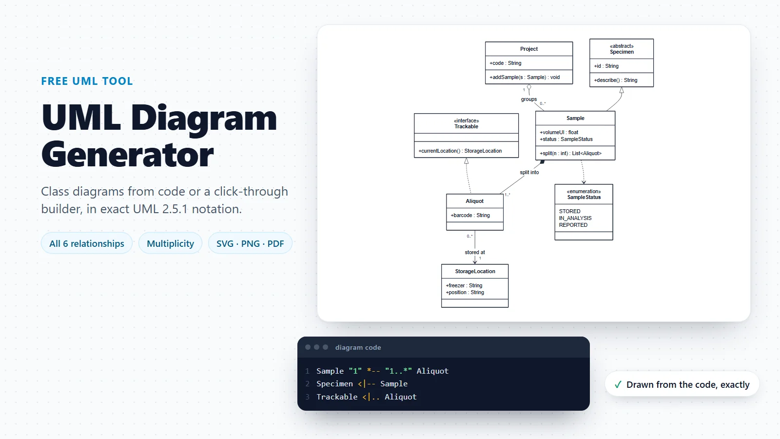
UML Diagram Generator
Class diagrams with every UML relationship, and a guide to the 14 UML diagram types.
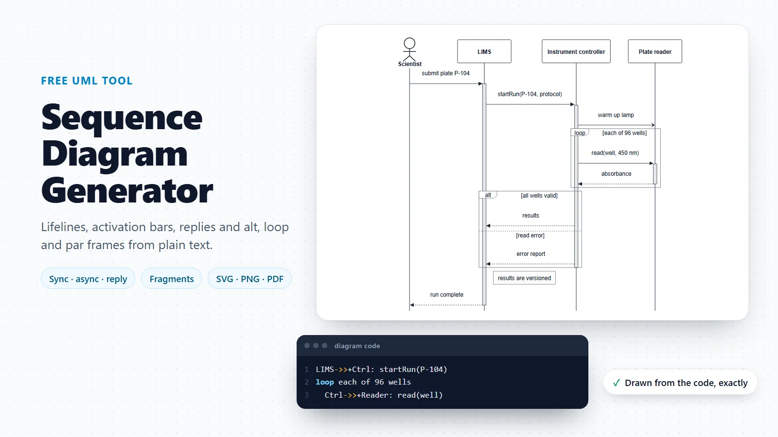
Sequence Diagram Generator
Messages between participants in time order, with activation bars and alt, opt, loop and par frames.

Workflow Diagram Generator
A flowchart of steps and decisions, when the boxes are actions rather than states.
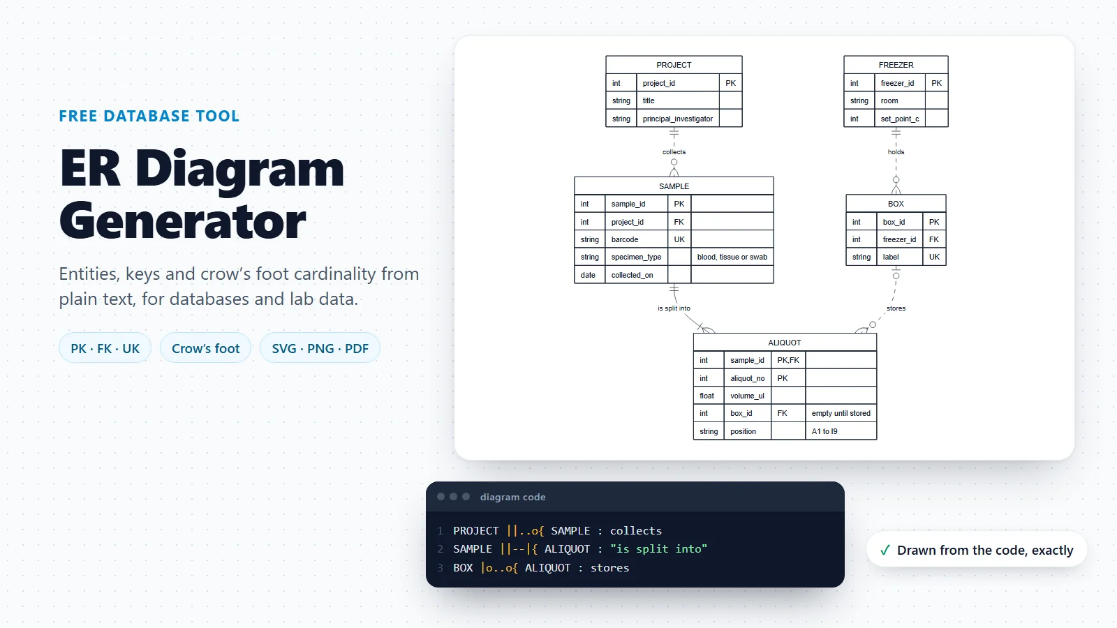
ER Diagram Generator
The data model behind a lifecycle: the sample record whose status a state machine describes, with keys and cardinality.
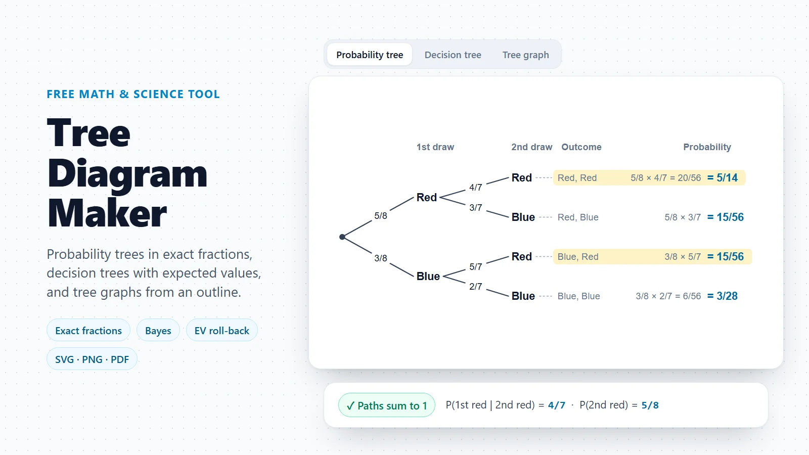
Tree Diagram Maker
Decision trees with expected values and probability trees, for choices that branch but never loop back.
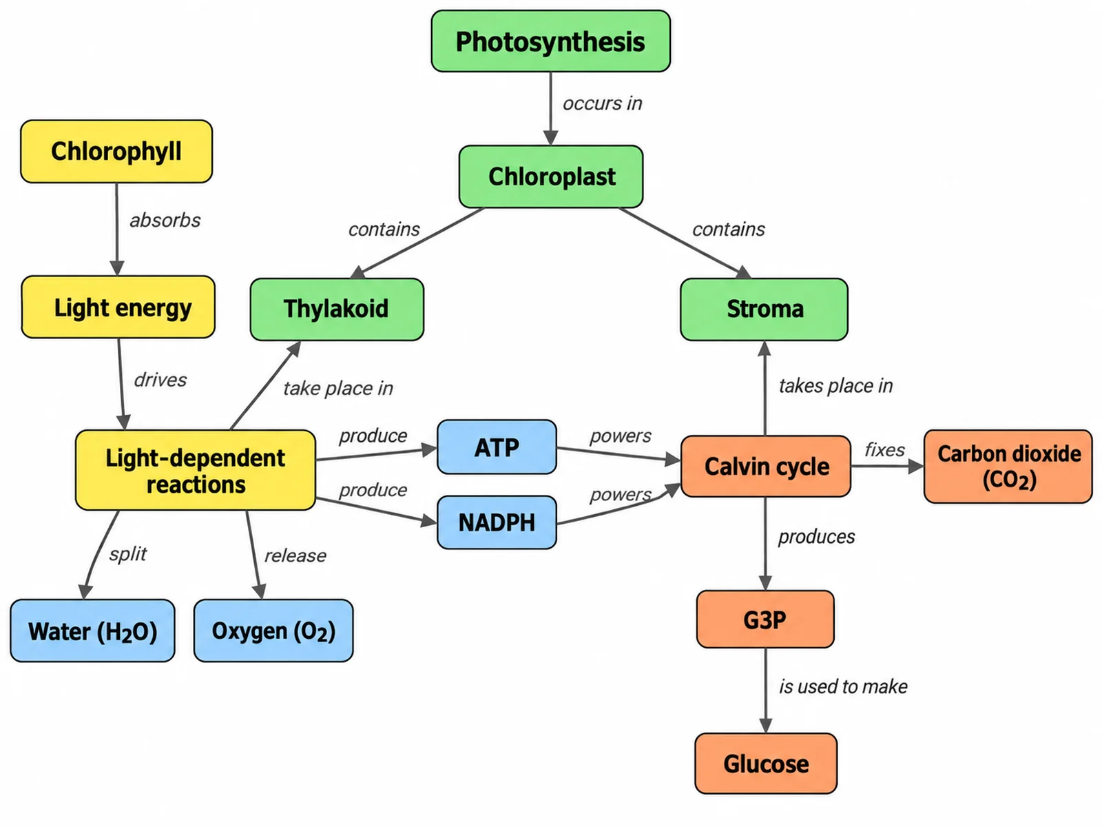
Concept Map Generator
Concepts and their relations with labelled arrows, for teaching and planning.
Drawing a procedure rather than states?
If the boxes are steps that happen one after another, a flowchart is the right diagram. The workflow diagram generator turns a short description into one.
Open the workflow diagram generatorLast checked: November 17, 2026. Sources: Object Management Group, UML 2.5.1 specification, clause 14 StateMachines; Harel, Statecharts: a visual formalism for complex systems (1987); RFC 9293, Transmission Control Protocol (TCP), connection state diagram; OpenStax, Biology 2e, 10.3 Control of the Cell Cycle; Mermaid state diagram syntax. The instrument and sample templates are illustrative models, not the firmware of any real device.